Small desktop 3D printers are already a familiar sight to industry and consumers alike. The increasing proliferation of different additive manufacturing technologies has also awakened interest in larger-scale printing possibilities. A few years ago, we reported in a blog post that the demand and supply of larger 3D printing devices has increased. The previous article (Finnish only, sorry) can be found at: https://blogi.savonia.fi/3dtulostus/2019/12/13/formnext-2019-suuret-muovitulostimet/
What is the largest 3D printed part in the world right now?
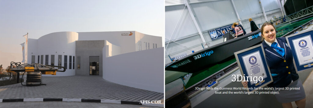
Defining the largest 3D-printed piece is challenging because many 3D-printed structures and pieces are made up of several separate 3D-printed parts. For example, on the construction side, 3D-printed bridges and houses often consist of modules that are manufactured one at a time at the factory and finally connected to each other. In the Guinness Book of Records, the largest 3D-printed structure (volume) is considered to be a 3D-printed building (manufactured in 2019) <source1> <source2> . On the other hand, the largest 3D-printed solid object is a “3Dirigo” boat manufactured 2019 by University of Maine <source>. It is not a coincidence that both of these largest parts were manufactured couple of years ago because COVID-19 epidemic affected 3D-printing companies as well and the industry is only now starting to pick up the pace once again. In March 2022, University of Maine has reportedly already broken that record by printing two new large-scale boats developed for the U.S. Marine Corps. One of the boats can carry two 20-foot shipping containers and the other can transport an entire rifle squad. They have not yet published any photos or technical details due to national security concerns, so the official record is still the boat from 2019.
Printing very small or very large parts can be challenging. 3D-printing is done by slicing the 3D-model vertically in separate layers and creating a suitable tool/print path for each layer before sending the information to the 3D-printer. Typical layer heights in “normal size” 3D-printing applications is 0.1 – 0.3 mm for plastics and with 30-50 µm for metals (selective laser melting). Keeping that in mind, just scaling up the printing area is not going to work – unless you are prepared to wait ages for the print job to complete. In order to avoid long printing times, something must be changed and that is usually both the material deposition rate and the layer height. Material extrusion is the most commonly used 3D-printing technology for manufacturing large parts, though some manufacturers claim that their vat photopolymerization systems are scalable as well. For material extrusion systems, increased deposition rate and layer height require larger nozzles. Typical desktop printers have nozzle diameters of 0.2-1 mm, while large scale systems significantly larger ones, usually something around 5-12 mm.
The above examples of the world’s largest 3D-printed objects are good examples of print jobs that require faster build rates. The concrete building in Dubai is 9.5 meters tall with an area of 640 square meters but it was printed in only three weeks. 3Dirigo, on the other hand, is 7.62 meters long and was printed with a plastic-wood cellulose composite in 72 hours. You can find more information (including time-lapse videos) from Apis Cor and University of Maine.
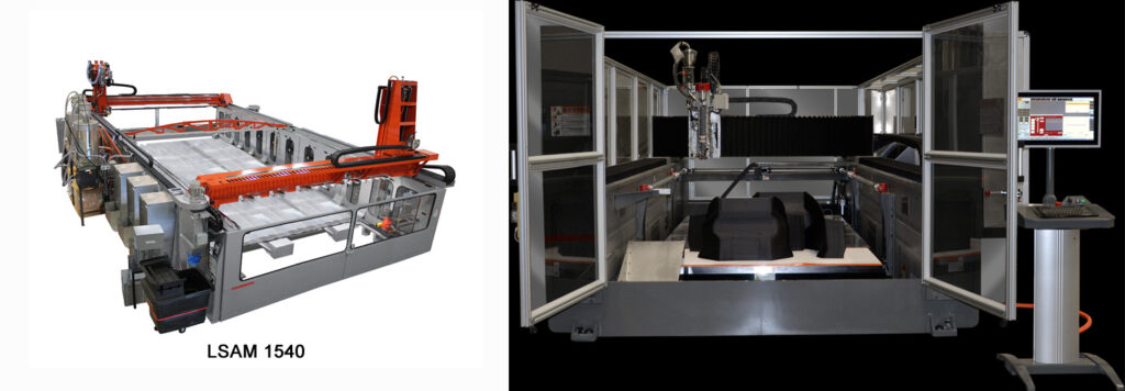
Currently there are few options for large-scale 3D-printing equipment. Two widely known manufacturers for large-scale printing systems are Thermwood and Cincinnati. Thermwood calls its systems LSAM (Large-Scale Additive Manufacturing) systems while Cincinnati Inc. has a BAAM (Big Area Additive Manufacturing) system. Both Thermwood and Cincinnati offer fixed, large-scale equipment that allows large-scale 3D-printing in controller environment. BAAM is installed on a base of high-speed laser cutting system and allows for a work area of 6 x 2.2 x 1.8 m. Largest LSAM systems has a work area of 3 x 6 x 3 meters.
In addition to these manufacturers, several companies offer 3D-printing “tool heads” for robots that make it possible to use regular industrial robots for 3D-printing. Both approaches have benefits and cons. A fixed environment allows for better controller printing process that is especially important when printing challenging materials. 3D-printing toolhead on an articulated robot, on the other hand, is a more cost-efficient way to start printing large-scale. It also makes it possible to use the robot cell to other purposes than 3D-printing, which makes it a perfect solution for universities and R&D institutions.
Savonia completed an extensive 3D-printing investment and development project during 2021. As part of the investment project, Savonia acquired robotic 3D-printing systems for metal, plastic and concrete. This blog post describes a work process for Savonia’s robotic 3D-printing system for plastic and composite materials.
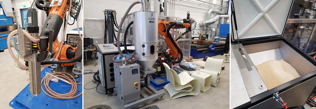
Savonia’s robotic 3D-printing workcell consists of CEAD robotextruder, granulate dryer and KUKA KR-120 robot. CEAD is a relatively well-known equipment manufacturer for stand-alone printheads under the brand name cead robotextruder (https://robotextruder.com/). CEAD’s 3D-printing equipment consist of the print head, a material supply unit and a separate drying unit that can be connected to the material supply unit. Drying of the material is an important property, as the granular material easily absorbs moisture from the air. This is especially noticeable with wood fiber composites. The system installation and implementation was delayed by a year due to the COVID and took place at the beginning of last year.
Robotic 3D-printing process
Material extrusion based robotic 3D-printing differs from basic 3D-printing mainly in terms of robot/environmental management. The mechanical operation of the print head is simple – granular material is fed into a heated screw, which melts and pushes the molten mass out of the print head. Print head is then moved along the print path resulting into the printed geometry.
The sheer amount of material used in the robotic printing makes temperature control of the printed part (and surrounding environment) more challenging. Although the cead robotextruder can print up to 12 kg per hour, the basic printing speed is limited to a few kilograms per hour due to the required temperature control of the basic materials. Higher material feed is not useful if the printed structure does not hold up, or if its quality is unsuitable for the intended use.
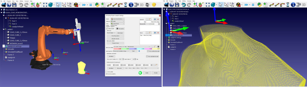
Savonia’s system does not include a specific printing platform, as the manufacturer did not yet have that available. This has later changed, and cead offers printing platforms with their systems. This poses challenges for some materials and in some work environments (such as halls) when the printing media does not adhere to the tray when it cools. In the initial stage, the printing platform was simply a pallet with a plywood top, and the first printed layer was stapled to it during the printing process. The actual printing process starts by opening the 3d-printable geometry in RoboDK, which is a software that is used in Savonia to create print paths for the robot. RoboDK (https://robodk.com/) is a general-purpose robot simulation program that enables remote programming of robots for many different uses, and the also includes modules for 3D printing.
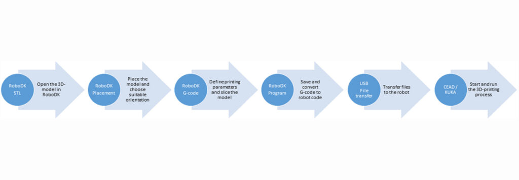
The part is placed in the desired position and orientation in the RoboDK virtual robot cell. It is recommended that the 3D model is already saved in the correct print orientation before opening it in RoboDK because that would mean less work when setting up the part on the RoboDK side.
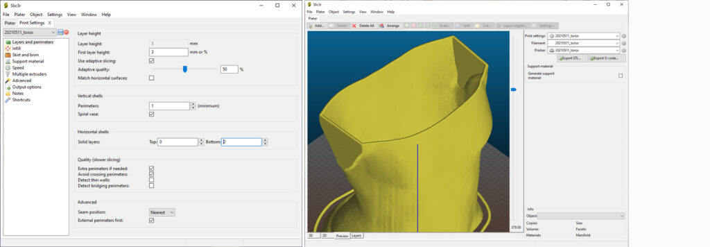
RoboDK uses a well-known, “general purpose” open source Slic3r program for slicing. The program is familiar from most of the desktop printers and specifies the printing parameters related to slicing. RoboDK translates the G-code generated by Slic3r into RoboDK instructions lines, which in turn are stored via a postprocessor in a format understood by the robot. Saved files can be transferred either through the network or via a USB stick to the robot.
What is Slicer?
A slicer is a program that, as its name implies, slices a 3D printable piece into the layered format of a 3D model. The number of layers and other related settings can be specified in the Slicer settings. Many commercial 3D printing programs use open source shredders like Slic3r.
What is a G-code?
The G-code is the trajectory and command instructions of the part to be printed in machine-readable form. 3D printers based on linear paths (such as desktop printers sold to consumers) read the G-code generated directly by the slicer, but determining robot speed and trajectory with articulated robots is more complicated. The robot needs at least the following information for each movement point: coordinate point location, position (orientation) of the tool and the position of the joints (configuration). The translation of the G code into a format understood by the robot takes place by means of a postprocessor.
What is a Postprocessor?
A postprocessor (PostScript) is a program, and in the case of RoboDK, a python script that reads a program made by a RoboDK and translates it into a format understood by the KUKA robot. At the same time, it can rewrite and comment the code for better readability in case there are challenges / problem areas in the print run that need to be resolved afterwards. In general, useful information includes information on which layer is moving, the length of the layer, the change in the speed of the movement or the material feed, etc. If there are problems with the printing process, this information could be used to access the root causes of the problems more quickly.
3D-printing a human sized mannequin
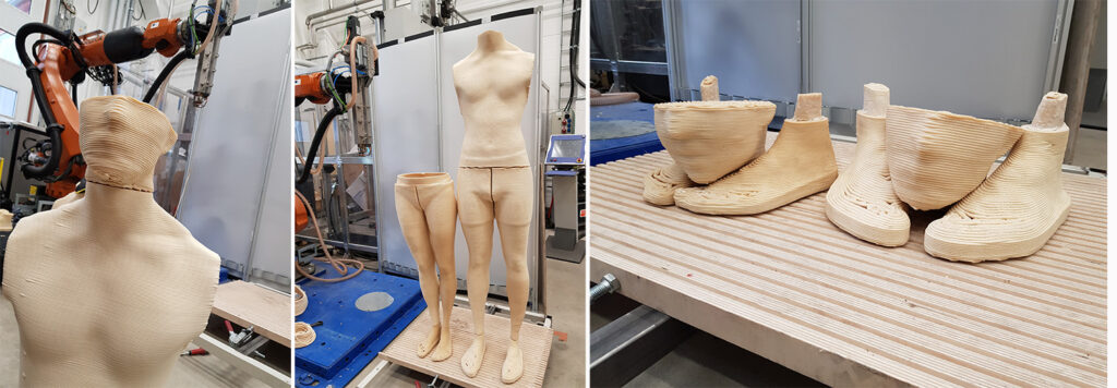
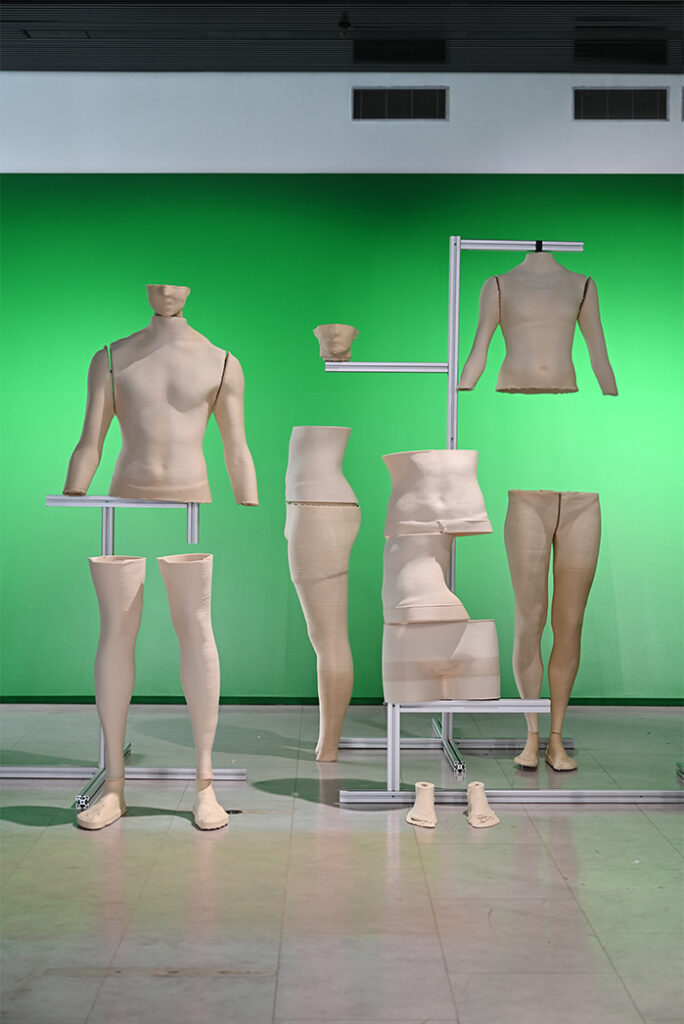
In 2021, Savonia participated in a demonstration project where the idea was to 3D-print a mannequin with custom geometry for the Helsinki Fashion Show 2021 installation. The project was a collaboration with Glasshouse Helsinki, UPM, Tampere University of Applied Sciences and Savonia University of Applied Sciences.
Mannequins were printed with UPM Formi wood-cellulose composite material and the installation was implemented by Florencia Colombo and Ville Kokkonen. It was on display at Glasshouse Helsinki premises during the Fashion Week 2021.
The printed 3D-geometries were provided by Ville Kokkonen. Because mannequins are used to display clothes, the models must be split in separate parts that can be assembled later. The print process also required some slight changes to 3D-geometries to enable self-supporting print process without separate support structures.
One of the challenges when printing with granulate extrusion systems similar to CEAD robotextruder is that material “retraction” is not possible. The material is melted in the screw and even if you pause, the extrusion process there will be some excess material dripping from the nozzle. In filament-based systems retract is used whenever the print head jumps to next printing position. The only way to avoid material drips in a system like this is to use a “continuous print / vase mode”. As the name implies, in this mode printing is processed as one continuous movement instead of the normal layer-by-layer process. In normal print mode each layer is printed as a separate step (start printing – print the layer – stop printing – move to next layer – start printing …), resulting a short stop between the layers and. Depending on print settings and geometry the start/stop points of each layer might vary.
Time-lapse video of the printing process
To prevent viewers from excess boredom, we have only included the print process of two torso parts. You can see the video here:
Time-lapse video of the printing process
Antti Alonen
R&D Adviser
Savonia University of Applied Sciences

Recent Comments